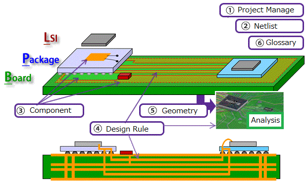
The LPB format (IEC 63055 / IEEE 2401-2015) is a standard to distribute information for LPB design . It consists of the following five data formats.(Sample file、Version3.0 Preview)。

- M-Format : Project Management
- N-Format : Netlist. Define connection information between parts
- C-Format : Component definition. Define design constraints, component footprints, and models for simulation
- R-Format : Design rule. Define rules such as board structure and line & space
- G-Format : Geometry. Graphic data representing Layer Stackup structure (2D) such as printed circuit board and IC package
What is LPB CFormat ?

CFormat is a container of the physical shape of the part and the simulation model.

The cross-reference between the part terminal (FootPrint) and the model input/output node is defined in CFormat file.

EDA tools can be read CFormat directory. And CFormat can be converted to library file of EDA tools.
Please see "How to use CFormat" for detail about CFormat.
If you have any question , please contact us from this mail form.
The detail of JEITA LPB Format
Please refer to here for the details of the design flow using LPB Format.
Challenges in the design

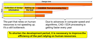
Due to advances in computer speed and algorithms, CAD / EDA processing is getting faster every year. However, a period of time spent collecting design information and configuring EDA tools is still a bottleneck as it relies on human resources.
The aim of LPB Format

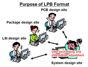
Recent design styles have shifted to horizontal international specialization. In this style, a system is designed by several design houses having own design culture. We should adjust manually the following differential of design house's culture.
- Difference in form of design specification.
- Difference in file format of EDA tool to use.
- Difference of technical terms
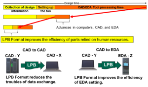
The ratio of such kind of work that dependent on human resources is increasing year by year. The aim of LPB Format reduces the waste of time of the design process. It improves the efficiency of the following time consuming works.

- Collecting of simulation model.
- Setting of CAD/EDA tools.
- Data exchange between CAD/EDA tools.
